Print, Wire, Drive: Bringing Your Robot to Life
Go-Kart in a Shoebox
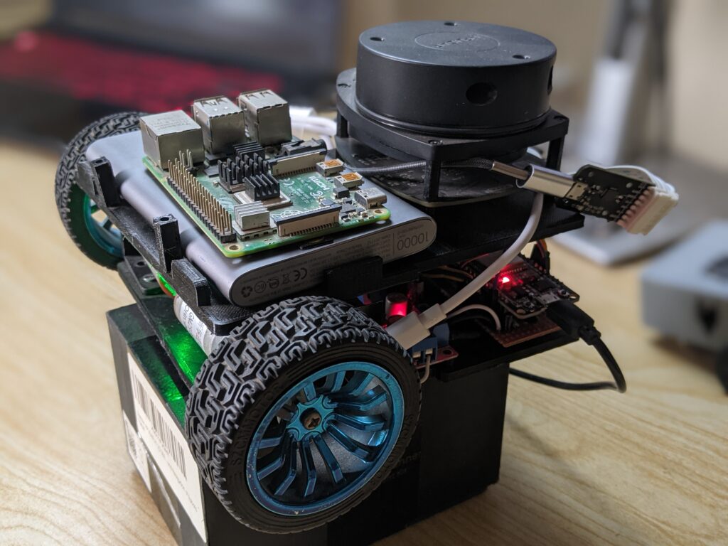
Picture this: a small robot, the size of a shoebox, zooms across your workshop floor, stopping before a wall, rotating, and rolling away as if it knows exactly where it is headed. You built it. Today’s post reveals how to 3D print robotics hardware and create the physical body of the bot—from frame to engine control, so your programming has something actual to propel.
You are not just printing plastic or connecting wires. You are creating the starting point of self-dependence. This is where code meets hardware; this guide ensures that your first robot does not only exist but prospers as a testbed for ROS 2-based autonomy. Whether you’re prototyping a ROS2 robot for research, education, or a startup prototype, this build will give you a clean, modular, and field-proven baseline for real-world testing.
Component Cast: Why Each 3D Print Robotics Hardware Part Matters
| Part | One-Line Analogy | Role in Autonomy |
| 3D-Printed Base | Car chassis frame | Holds every other part square and level. |
| Wheels + Encoders | Tires with built-in odometer | Provide grip and tell the brain how far you rolled. |
| Caster Wheel | Shopping-cart swivel | Lets the rear slide smoothly while front wheels steer. |
| L298D Motor Driver | Electronic throttle & gearbox | Converts brain signals into motor power. |
| ESP32 | On-board mechanic | Sends speed commands, reads encoder ticks in real time. |
| Li-Po Cells × 3 | Fuel tank | High-current burst for motors and brain alike. |
| Power Button | Ignition key | Safe on/off; saves Li-Po from deep discharge. |
| 2-D LiDAR | Radar dish | Scans 360° to spot walls and obstacles. |
| Raspberry Pi 4 | Co-driver with the map | Runs Linux + ROS 2, fuses sensor data and plots routes. |
Every component above plays a critical role in 3D print robotics hardware; they’re not just for show. Autonomous systems fail when hardware and software are misaligned. A tight integration of accurate encoders, robust motor control, and smart compute creates the feedback loop necessary for true autonomy.
Assembly Flow: Like IKEA, But Smarter
Follow this assembly path for a clean build:
1. Print & Prep the Frame
Use 3D print robotics hardware with PLA or PETG for durability. Print with at least 40–50% infill. Sand the edges smooth to remove artifacts and insert M3 nuts into embedded slots while the plastic is warm (or heat them in with a soldering iron). Pre-threading saves time and frustration later. Reinforce load-bearing surfaces with additional wall thickness or infill as needed.
2. Bolt Motors + Wheels
Mount the DC gear motors and ensure encoder wires are routed inward. Attach wheels snugly — balance is key for straight-line motion. Use thread lock if necessary; vibration can loosen nuts over time. Confirm encoder disks rotate freely with the wheel and there’s no axle slippage.
3. Mount L298D on Standoffs
Position the L298D close to the motors for short wire runs. Elevate it using standoffs for airflow and accessibility. Keep enough slack for multimeter probing during future debugging.
4. Wire Power Path
A clean power system avoids noise, brownouts, and random resets. Use:
- Li-Po → XT60 → Toggle Switch
- Switch → 5V Buck Converter
- Buck → Raspberry Pi and ESP32
Add fuses and proper gauge wiring. Use soldered connections and heat-shrink tubing for safety. Diagram everything before you solder.
5. Seat the ESP32
Connect ESP32 GPIOs to L298D motor inputs. Enable PWM on ENA/ENB pins for speed control. Optionally, use serial UART to link with Raspberry Pi for command and feedback exchange.
6. Snap on LiDAR & Raspberry Pi
Secure the Raspberry Pi on the upper frame tier. Connect the LiDAR via USB. Ensure cables are firmly attached and routed away from motor wires to avoid EMI interference. Zip ties or custom clips help maintain a clean internal layout.
7. Smoke Test
Before any software, power on the hardware. Check:
- LEDs on ESP32 and L298D
- Voltage across Pi and buck converter
- No overheating or loose wires
A digital multimeter is your best friend here. Don’t skip this.
First Drive: Pushing the Trolley Out of the Garage with 3D Print Robotics Hardware
Start simple. Upload this ESP32 code to verify motor wiring and direction:
#define ENA  25
#define IN1  26
#define IN2  27
#define ENB  14
#define IN3  12
#define IN4  13

void setup() {
  pinMode(IN1, OUTPUT); pinMode(IN2, OUTPUT);
  pinMode(IN3, OUTPUT); pinMode(IN4, OUTPUT);
  ledcSetup(0, 1000, 8); ledcAttachPin(ENA, 0);
  ledcSetup(1, 1000, 8); ledcAttachPin(ENB, 1);
  ledcWrite(0, 128); ledcWrite(1, 128);
  digitalWrite(IN1, HIGH); digitalWrite(IN2, LOW);
  digitalWrite(IN3, HIGH); digitalWrite(IN4, LOW);
}

void loop() {}
Run the robot on blocks. Make sure both wheels spin consistently and in the same direction. Adjust pin assignments or motor leads if needed. Small misalignments now can throw off navigation later, especially when working with 3D print robotics hardware.
Connect the Dots: How Hardware Enables Autonomy
Everything you just built enables ROS2-based intelligence to function in the real world:
- Motion Control: ESP32 interprets velocity commands and runs PWM-controlled outputs.
- Sensor Feedback: LiDAR maps surroundings, while encoders confirm how far the robot has moved.
- Computation: Raspberry Pi runs ROS2 nodes, building maps, running logic, and planning movement.
- Power: Central to system stability, clean power avoids resets and hardware failures.
This flow models full-scale autonomous systems. If it works here, you’re learning skills transferable to industrial AMRs, research bots, and more.
What’s Next
Once the hardware moves smoothly, you’re ready to:
- Integrate ROS 2 nodes and control topics
- Launch real-time encoder monitoring and LiDAR scanning
- Create URDF robot models for simulation
- Set up SLAM or autonomous navigation pipelines
Building the hardware is just the beginning. A well-structured base ensures that every future layer, from software to sensors , has a strong foundation to build on.
Learn More and Build Confidently
At Robotisim, we publish expert-driven content to help developers like you explore the real edge of 3D print robotics hardware. From ROS2 integration tips to microcontroller interfacing, every tutorial and guide reflects the standards we use in our own labs.
Visit Robotisim to deepen your robotics journey. Whether you’re exploring how to 3D print robotics hardware for research or building a ROS2-based platform from scratch, you’ll find advanced resources to power your next breakthrough.